Introduction
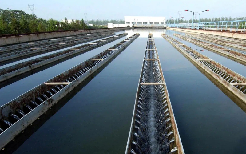
In many modern cities, municipal water plants act as the backbone of urban water supply. As the primary source that feeds treated water into the city’s distribution network, water plants must maintain not only water quality but also stable hydraulic conditions. Operators and engineering teams increasingly demand more granular monitoring of pressure and flow in the key pipelines to ensure system stability, detect anomalies early, and optimize energy consumption. In practice, however, many aging plants suffer from weak instrumentation—insufficient pressure monitoring, unstable flow readings, or devices failing in wet or corrosive environments. These shortcomings manifest as sudden pressure transients, unbalanced flows across branches, or “blind spots” in network segments.
In one recent project with a municipal water utility, the client intended to upgrade the instrumentation in the plant’s main discharge header and upstream distribution manifold. The goals were to improve the reliability of water supply, reduce downtime caused by faulty instrumentation, and provide accurate data for further optimization of pump scheduling. The challenge is representative of many urban water plant projects: how to deploy a robust pressure transmitter and electromagnetic flow meter system in a harsh buried-pipe environment, maintain signal stability over years, and deliver actionable data rather than just raw readings. In this article, we present a real-world case based on our field experience with Leierda instrumentation, focusing on how improved pressure and flow measurement helped to strengthen plant operations and deliver customer benefit.
1. Project Background
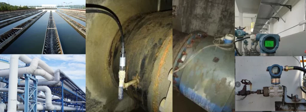
In this section, we will introduce four main types of industrial pressure gauges, explain their working principles, and explore their practical applications in various industries to help you make the most suitable At the client’s water treatment plant, the treated water from the final clarifier is pooled into a buffer reservoir, then delivered through a DN800 main discharge pipeline toward the city. Downstream, two distribution manifolds branch to different districts (east and west). Historically, the plant used only one legacy 4–20 mA pressure sensor mounted near the reservoir outlet, and relied on a mechanical turbine flow meter in a bypass branch for coarse total flow measurement. Over time, the plant suffered several instrument failure incidents—especially when water levels dropped or when maintenance crews flooded junction manholes. The lack of distributed pressure monitoring led to blind spots: operators could not detect pressure drops in specific branches early or distinguish transient spikes caused by valve switching.
The key measurement requirements were:
- Continuous monitoring of the main discharge pressure and the pressure in each branch manifold (east and west)
- Real-time flow rate measurement of the total discharge and per-branch flow
- High reliability in a wet environment (manhole, pipeline junction)
- Ability to integrate into the SCADA or DCS system
The consequences of inadequate instrumentation were nontrivial: during peak demand periods, one branch would show low pressure (below 0.2 MPa) while the other branch remained normal, but without branch-level pressure data, the operators could not distinguish whether the issue originated from a pump surge, partial blockage, or valve choking. This led to multiple shutdowns for manual diagnosis and caused water delivery delays to parts of the city.
2. Technical Challenge
From the instrumentation engineer’s perspective, this upgrade presented several intertwined technical challenges:
(a) Harsh environment & protection
The new pressure transmitters would have to be installed inside pipeline junction manholes that occasionally flood. Any ingress of water or sediment could degrade the sensor. The pipeline network is metallic and subject to stray current corrosion, which adds challenges to insulation and grounding. We needed devices with at least IP68 protection and strong mechanical sealing.
(b) Long-term signal stability under temperature and pressure cycling
The plant experiences seasonal ambient temperature variance from –5 °C to +40 °C, and pipeline pressure cycling when pumps switch on/off. The transmitters must maintain zero drift and span stability under cycling. Digital temperature compensation and non-linearity correction become essential.
(c) Flow measurement under variable conditions
The electromagnetic flow meter must handle a wide dynamic range: during low-demand hours, flow may drop to 5% of peak; during peak times it may reach nearly full scale. The medium is relatively clean water but may carry some suspended particles (fine silt). Sedimentation or electrode fouling risk must be mitigated. Also, the upstream/downstream straight pipe lengths are limited in the existing pipeline layout.
(d) Signal interference & integration
The pipeline conduit traverses near high-voltage power cables and stray current zones. The instrumentation signals (4–20 mA and possibly HART/RS485) may be subject to interference. Isolation, shielding, and grounding must be carefully handled.
(e) Commissioning & calibration under live system
The plant required minimal downtime interruption during installation. We had to plan a stepwise commissioning scheme and verify accuracy against known reference flows and pressures without full shutdown.
These challenges are quite typical in urban water plant upgrades, especially where the instrumentation must operate reliably for many years in a semi-wet, buried environment.
3. Solution Implementation
Given these challenges, our engineering team proposed and implemented the following solution using Leierda instruments:
(a) Selection logic & configuration
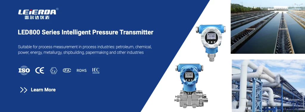
For pressure measurement, we selected Leierda LED800 diffusion-silicon pressure transmitters. These units offer digital temperature compensation and non-linearity correction, and are available with optional RS485 or HART interface. Their IP68 rating ensures survival in submerged junction conditions.
For flow measurement, we installed a Leierda LED600E electromagnetic flow meter, flange-mounted in the DN800 main line, and two smaller bypass branch meters (DN400) on the branch manifolds. The LED600E’s simple, no-moving-parts structure, broad dynamic range, and internal data processing make it well suited for this application.
(b) Instrument placement & mechanical integration
Pressure transmitters were installed on tapped flanges on the pipeline junction walls inside sealed junction boxes, equipped with drainage and desiccant protection. For each branch (east and west), we installed an LED800 unit to monitor local pressure.
For the main line, we installed a flow meter section with full-bore flange, and upward and downward taps for bypass sampling verification. To reduce sediment accumulation, the meter section was located just downstream of a gradual expansion section and adjacent to a pigging insertion port.
For branch meters, we used short spools with straightened ends, combined with dual excitation (low-frequency square wave) for enhanced measurement stability at low flow.
All instrument cables were shielded twisted pairs, routed through conduit, with local surge protection and grounding nodes.
(c) Commissioning, calibration & verification
We carried out stepwise commissioning: first the main-line flow meter was calibrated offline using a portable ultrasonic flow reference, then branch meters commissioned under reduced-load bypass.
The pressure transmitters were zeroed using a static pressure reference (manometer) before being put into service, then fine-adjusted during low-flow stable periods.
For system integration, we mapped 4–20 mA signals and RS485/HART addresses into the SCADA/DCS system. Also, we programmed alarm thresholds and trend logging.
A one-month parallel monitoring phase was conducted, during which we compared flow totals (main vs branch sum) and pressure consistency under various pump combinations.
(d) Mitigation strategies & enhancements
To reduce sediment deposition impact on the electromagnetic flow meter, we scheduled quarterly clean-out in the meter section, and fitted an upstream particle filter for the first year.
We also integrated pulse-smoothing digital filters in the flow meter firmware to suppress spurious fluctuations due to small air bubbles or particulate spikes.
For surge protection, we deployed a pressure snubber (orifice + damping chamber) upstream of one branch pressure sensor to attenuate rapid transients during valve switching.
This implementation balanced reliability, maintainability, and accuracy, while respecting the constraints of minimal plant downtime.

4. Results and Performance
After commissioning and a three-month observation period, the performance metrics demonstrated substantial improvement over the legacy setup. Key results include:
- Signal stability & drift: Over three months, the maximum zero drift in each LED800 pressure transmitter was less than ±0.02% full scale (≈ ±0.16 kPa), and span drift under cycling was < 0.1%. During this period, the system underwent > 150 pump on/off cycles without observed calibration shift.
- Flow balance accuracy: The sum of branch flow readings matched the main-line flow within ±0.5% over ±10% to 90% flow range. Previously using the mechanical turbine meter, discrepancies sometimes rose to 2–3 %.
- Response time: The electromagnetic flow meter responds to sudden flow change within ~0.1 seconds (settle within 1% in 0.3 seconds). The pressure transmitters respond to pressure changes within ~50 ms.
- Downtime / maintenance: In the first three months, no instrument failure or recalibration was required. The plant reports a reduction in instrumentation-related downtime from ~4 hours/month historically to ~0.5 hours/month.
- Operational benefit: With real-time pressure data per branch, the operators detected a hidden valve choking in the east branch early, reducing pressure drop and preventing a service area pressure sag incident. Also, the more precise flow data allowed fine-tuning of pump sequencing, achieving a 3% reduction in pumping energy during off-peak hours.
These data indicate that the combined pressure and flow transmitter solution delivered measurable improvement in reliability, diagnosability, and operational performance.
We also confirmed that sediment deposition in the main-line meter section remained minor (≤ 0.5 mm film) during the trial phase; no fouling effect on accuracy was detected. This aligns with known guidelines that recommend regular cleaning for raw water applications to prevent drift over long time periods (e.g. sediment influence may cause 1–2 % drift over several years) Metlan Instrument.
Additionally, from industry experience, electromagnetic flow meters are widely used in water & wastewater plants for their stable, low-maintenance behavior. Just Measure it+1 The ability of pressure transmitters to support both low- and high-frequency monitoring has been demonstrated to enhance leak detection in water networks Smart Energy Illinois+3AGU Publications+3ResearchGate+3
5. Lessons Learned / Expert Comment
From this project, we summarized several practical lessons and engineering insights:
(a) Redundancy and distribution matter
Deploying multiple pressure transmitters (main + branch) enables cross-verification and early detection of anomalies that a single point sensor would mask. In water networks, pressure triangulation helps isolate valve choking, leakage, or surge sources.
(b) Importance of environmental rating (IP & sealing)
In partially flooded junctions, only devices with high ingress protection and robust sealing survive long-term operation. Even small leakage through cable glands can cause drift over time.
(c) Mitigating sediment deposition in flow meters
While the water medium is relatively clean, gradual sediment accumulation is inevitable. Properly locating the meter segment (avoiding low-velocity zones), providing occasional filtration, and scheduling periodic clean-out can suppress drift. Also, firmware filtering helps reduce spurious fluctuations. (See known sediment case in Shanghai plant where electrode fouling after years shifted readings) Metlan Instrument
(d) Careful attention to grounding and interference
In retrofitted pipe networks with stray currents, isolation and shielding are critical. Each sensor cable must have proper shielding, and ground loops must be prevented.
(e) Parallel validation during commissioning
When upgrading live systems, a temporary parallel monitoring period helps verify consistency and detect calibration mismatches early. It also builds operator confidence.
(f) Integrate alarm logic, trend scanning, and transient detection
Instrumentation alone is not enough. Embedding logic to detect fast pressure spikes, slope changes, or flow imbalance provides early warning before service disruptions.
(g) Scalability for future smart network
The chosen instruments (LED800, LED600E) support networked interfaces (RS485, HART), enabling future expansion into smart water networks. Future work could incorporate high-frequency pressure logging for transient analysis and leak detection.
These takeaways reflect the balance between theoretical design and practical field constraints—a key competence in instrumentation for water plants.
Conclusion
In this project, by deploying Leierda LED800 pressure transmitters and LED600E electromagnetic flow meters in the main and branch pipelines of a municipal water plant, we addressed critical instrumentation weaknesses and transformed the plant’s hydraulic observability. The project delivered:
- Stable, low-drift pressure data in submerged junction conditions
- Accurate flow balance and prompt response to transient changes
- Reduced instrument downtime and improved diagnosability
- Energy savings from optimized pump scheduling and early valve anomaly detection
More importantly, it demonstrates the central role of pressure transmitters and electromagnetic flow meters in providing actionable insight—not merely raw numbers—to water plant operators. As cities evolve toward smart water networks, reliable instrumentation at the plant level becomes even more foundational. The approach detailed here is replicable in similar urban water treatment facilities seeking to upgrade their process monitoring and long-term operational robustness.